For Daily Job Alert For Daily Job Alert |
Join Our Whats App Channel |
| For Free Study Material |
Join Our Telegram Channel |
Computer Networking Basics
Introduction To Computer Networks
Modern world scenario is ever changing. Data Communication and network have changed the way business and other daily affair works. Now, they highly rely on computer networks and internetwork.
A set of devices often mentioned as nodes connected by media link is called a Network.
A node can be a device which is capable of sending or receiving data generated by other nodes on the network like a computer, printer etc. These links connecting the devices are called Communication channels.
Computer network is a telecommunication channel using which we can share data with other coomputers or devices, connected to the same network. It is also called Data Network. The best example of computer network is Internet.
Computer network does not mean a system with one Control Unit connected to multiple other systems as its slave. That is Distributed system, not Computer Network.
A network must be able to meet certain criterias, these are mentioned below:
- Performance
- Reliability
- Scalability
Performance
It can be measured in the following ways :
- Transit time : It is the time taken to travel a message from one device to another.
- Response time : It is defined as the time elapsed between enquiry and response.
Other ways to measure performance are :
- Efficiency of software
- Number of users
- Capability of connected hardware
Reliability
It decides the frequency at which network failure take place. More the failures are, less is the network’s reliability.
Security
It refers to the protection of data from any unauthorised user or access. While travelling through network, data passes many layers of network, and data can be traced if attempted. Hence security is also a very important characteristic for Networks.
Properties of a Good Network
- Interpersonal Communication : We can communicate with each other efficiently and easily. Example: emails, chat rooms, video conferencing etc, all of these are possible because of computer networks.
- Resources can be shared : We can share physical resources by making them available on a network such as printers, scanners etc.
- Sharing files, data : Authorised users are allowed to share the files on the network.
Basic Communication Model
A Communication model is used to exchange data between two parties. For example: communication between a computer, server and telephone (through modem).

Source
Data to be transmitted is generated by this device, example: telephones, personal computers etc.
Transmitter
The data generated by the source system is not directly transmitted in the form its generated. The transmitter transforms and encodes the data in such a form to produce electromagnetic waves or signals.
Transmission System
A transmission system can be a single transmission line or a complex network connecting source and destination.
Receiver
Receiver accepts the signal from the transmission system and converts it into a form which is easily managed by the destination device.
Destination
Destination receives the incoming data from the receiver.
Data Communication
The exchange of data between two devices through a transmission medium is called Data Communication. The data is exchanged in the form of 0’s and 1’s. The transmission medium used is wire cable. For data communication to occur, the communication device must be a part of a communication system. Data Communication has two types – Local and Remote which are discussed below:
Local
Local communication takes place when the communicating devices are in the same geographical area, same building, or face-to-face etc.
Remote
Remote communication takes place over a distance i.e. the devices are farther. The effectiveness of a data communication can be measured through the following features :
- Delivery: Delivery should be done to the correct destination.
- Timeliness: Delivery should be on time.
- Accuracy: Data delivered should be accurate.
Components of Data Communication
- Message: It is the information to be delivered.
- Sender: Sender is the person who is sending the message.
- Receiver: Receiver is the person to whom the message is being sent to.
- Medium: It is the medium through which the message is sent. For example: A Modem.
- Protocol: These are some set of rules which govern data communication.
Uses of Computer Networks
Had it not been of high importance, nobody would have bothered connecting computers over a network. Let’s start exploring the uses of Computer Networks with some traditional usecases at companies and for individuals and then move on to recent developments in the area of mobile users and home networking.
Business Applications
- Resource Sharing: The goal is to make all programs, equipments, and especially data, available to anyone on the network without regard to the physical location of the resource and the user.
- Server-Client model: One can imagine a company’s information system as consisting of one or more databases and some number of employees who need to access them remotely. In this model, the data is stored on powerful computers called servers. Often these are centrally housed and maintained by a system administrator. In contrast, the employees have simple machines, called clients, on their desks, with which they access remote data.
- Communication Medium: A computer network can provide a powerful communication medium among employees. Virtually every company that has two or more computers now has e-mail (electronic mail), which employees generally use for a great deal of daily communication
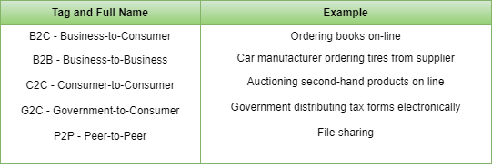
- E-Commerce: A goal that is starting to become more important is doing business with consumers over the Internet. Airlines, bookstores and music vendors have discovered that many customers like the convenience of shopping from home. This sector is expected to grow quickly in the future. The most popular forms are listed in the below figure:
Home Applications
Some of the most important uses of the Internet for home users are as follows:
- Access to remote information
- Person-to-person communication
- Interactive entertainment
- Electronic commerce
Mobile Users
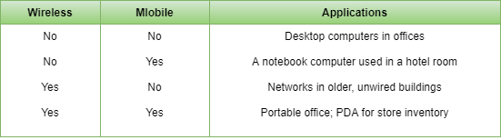
Mobile computers, such as notebook computers and Mobile phones, are one of the fastest-growing segments of the computer industry. Although wireless networking and mobile computing are often related, they are not identical, as the below figure shows.
Line Configuration in Computer Networks
Network is a connection made through connection links between two or more devices. Devices can be a computer, printer or any other device that is capable to send and receive data. There are two ways to connect the devices :
- Point-to-Point connection
- Multipoint connection
Point-To-Point Connection
It is a protocol which is used as a communication link between two devices. It is simple to establish. The most common example for Point-to-Point connection (PPP) is a computer connected by telephone line. We can connect the two devices by means of a pair of wires or using a microwave or satellite link.
Example: Point-to-Point connection between remote control and Television for changing the channels.

MultiPoint Connection
It is also called Multidrop configuration. In this connection two or more devices share a single link.
There are two kinds of Multipoint Connections :
- If the links are used simultaneously between many devices, then it is spatially shared line configuration.
- If user takes turns while using the link, then it is time shared (temporal) line configuration.
Types of Network Topology
Network Topology is the schematic description of a network arrangement, connecting various nodes(sender and receiver) through lines of connection.
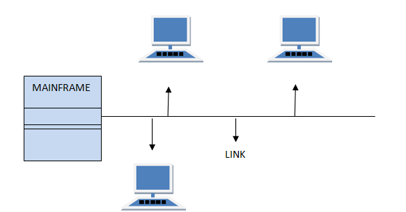
BUS Topology
Bus topology is a network type in which every computer and network device is connected to single cable. When it has exactly two endpoints, then it is called Linear Bus topology.
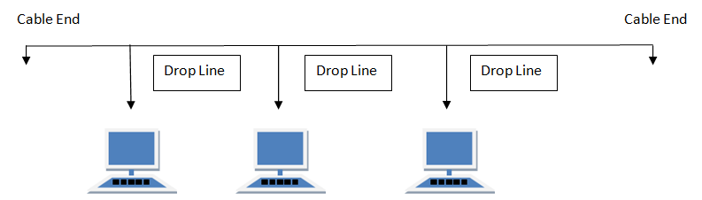
Features of Bus Topology
- It transmits data only in one direction.
- Every device is connected to a single cable
Advantages of Bus Topology
- It is cost effective.
- Cable required is least compared to other network topology.
- Used in small networks.
- It is easy to understand.
- Easy to expand joining two cables together.
Disadvantages of Bus Topology
- Cables fails then whole network fails.
- If network traffic is heavy or nodes are more the performance of the network decreases.
- Cable has a limited length.
- It is slower than the ring topology.
RING Topology
It is called ring topology because it forms a ring as each computer is connected to another computer, with the last one connected to the first. Exactly two neighbours for each device.
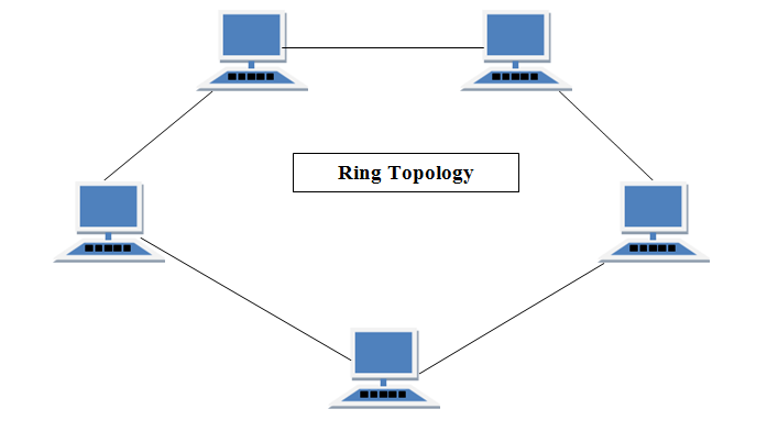
Features of Ring Topology
- A number of repeaters are used for Ring topology with large number of nodes, because if someone wants to send some data to the last node in the ring topology with 100 nodes, then the data will have to pass through 99 nodes to reach the 100th node. Hence to prevent data loss repeaters are used in the network.
- The transmission is unidirectional, but it can be made bidirectional by having 2 connections between each Network Node, it is called Dual Ring Topology.
- In Dual Ring Topology, two ring networks are formed, and data flow is in opposite direction in them. Also, if one ring fails, the second ring can act as a backup, to keep the network up.
- Data is transferred in a sequential manner that is bit by bit. Data transmitted, has to pass through each node of the network, till the destination node.
Advantages of Ring Topology
- Transmitting network is not affected by high traffic or by adding more nodes, as only the nodes having tokens can transmit data.
- Cheap to install and expand
Disadvantages of Ring Topology
- Troubleshooting is difficult in ring topology.
- Adding or deleting the computers disturbs the network activity.
- Failure of one computer disturbs the whole network.
To Clear English Sections You must Have English Tricks Book Buy Now From Here
Buy Now
To Clear Quantitative Aptitude Section You must Have Quantitative Aptitude Tricks Book Buy Now From Here
Buy Now
To Clear Reasoning Section You must Have Reasoning Tricks Book Buy Now From Here
Buy Now
To Clear Computer Awareness Section You must Have Computer Awareness Book Buy Now From Here
Buy Now
Puzzles & Seating Arrangement Short Tricks Book
Buy Now
STAR Topology
In this type of topology all the computers are connected to a single hub through a cable. This hub is the central node and all others nodes are connected to the central node.
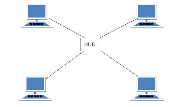
Features of Star Topology
- Every node has its own dedicated connection to the hub.
- Hub acts as a repeater for data flow.
- Can be used with twisted pair, Optical Fibre or coaxial cable.
Advantages of Star Topology
- Fast performance with few nodes and low network traffic.
- Hub can be upgraded easily.
- Easy to troubleshoot.
- Easy to setup and modify.
- Only that node is affected which has failed, rest of the nodes can work smoothly.
Disadvantages of Star Topology
- Cost of installation is high.
- Expensive to use.
- If the hub fails then the whole network is stopped because all the nodes depend on the hub.
- Performance is based on the hub that is it depends on its capacity
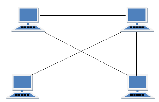
MESH Topology
It is a point-to-point connection to other nodes or devices. All the network nodes are connected to each other. Mesh has n(n-1)/2 physical channels to link n devices.
There are two techniques to transmit data over the Mesh topology, they are :
- Routing
- Flooding
Routing
In routing, the nodes have a routing logic, as per the network requirements. Like routing logic to direct the data to reach the destination using the shortest distance. Or, routing logic which has information about the broken links, and it avoids those node etc. We can even have routing logic, to re-configure the failed nodes.
Flooding
In flooding, the same data is transmitted to all the network nodes, hence no routing logic is required. The network is robust, and the its very unlikely to lose the data. But it leads to unwanted load over the network.
Types of Mesh Topology
- Partial Mesh Topology : In this topology some of the systems are connected in the same fashion as mesh topology but some devices are only connected to two or three devices.
- Full Mesh Topology : Each and every nodes or devices are connected to each other.
Features of Mesh Topology
- Fully connected.
- Robust.
- Not flexible.
Advantages of Mesh Topology
- Each connection can carry its own data load.
- It is robust.
- Fault is diagnosed easily.
- Provides security and privacy.
Disadvantages of Mesh Topology
- Installation and configuration is difficult.
- Cabling cost is more.
- Bulk wiring is required.
TREE Topology
It has a root node and all other nodes are connected to it forming a hierarchy. It is also called hierarchical topology. It should at least have three levels to the hierarchy.
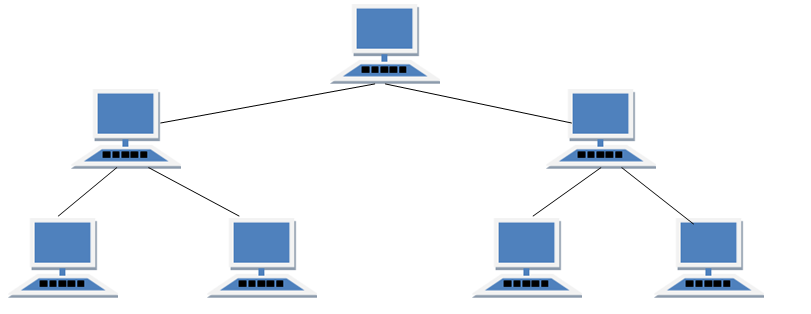
Features of Tree Topology
- Ideal if workstations are located in groups.
- Used in Wide Area Network.
Advantages of Tree Topology
- Extension of bus and star topologies.
- Expansion of nodes is possible and easy.
- Easily managed and maintained.
- Error detection is easily done.
Disadvantages of Tree Topology
- Heavily cabled.
- Costly.
- If more nodes are added maintenance is difficult.
- Central hub fails, network fails.
HYBRID Topology
It is two different types of topologies which is a mixture of two or more topologies. For example if in an office in one department ring topology is used and in another star topology is used, connecting these topologies will result in Hybrid Topology (ring topology and star topology).
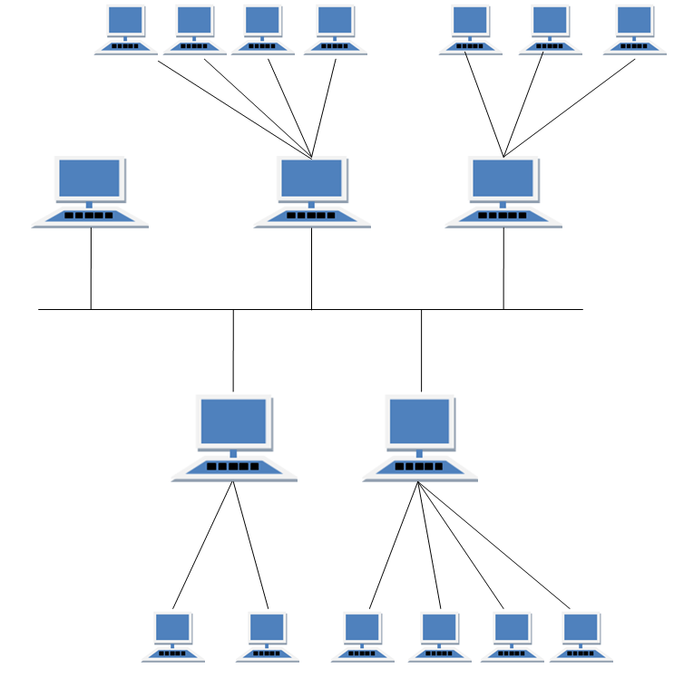
Features of Hybrid Topology
- It is a combination of two or topologies
- Inherits the advantages and disadvantages of the topologies included
Advantages of Hybrid Topology
- Reliable as Error detecting and trouble shooting is easy.
- Effective.
- Scalable as size can be increased easily.
- Flexible.
Disadvantages of Hybrid Topology
- Complex in design.
- Costly.
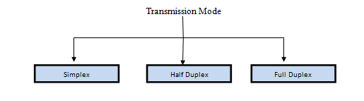
Transmission Modes in Computer Networks
Transmission mode means transferring of data between two devices. It is also called communication mode. These modes direct the direction of flow of information. There are three types of transmission mode. They are :
- Simplex Mode
- Half duplex Mode
- Full duplex Mode
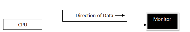
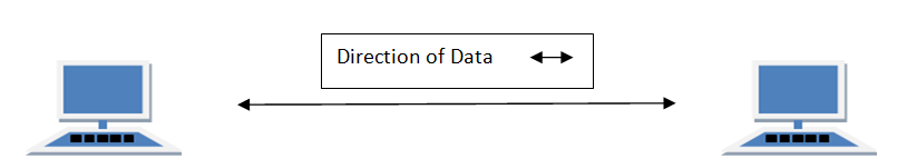
SIMPLEX Mode
In this type of transmission mode data can be sent only through one direction i.e. communication is unidirectional. We cannot send a message back to the sender. Unidirectional communication is done in Simplex Systems.
Examples of simplex Mode is loudspeaker, television broadcasting, television and remote, keyboard and monitor etc.
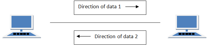
HALF DUPLEX Mode
Half-duplex data transmission means that data can be transmitted in both directions on a signal carrier, but not at the same time. For example, on a local area network using a technology that has half-duplex transmission, one workstation can send data on the line and then immediately receive data on the line from the same direction in which data was just transmitted. Hence half-duplex transmission implies a bidirectional line (one that can carry data in both directions) but data can be sent in only one direction at a time.
Example of half duplex is a walkie- talkie in which message is sent one at a time and messages are sent in both the directions.
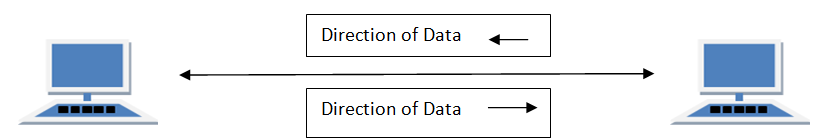
FULL DUPLEX Mode
In full duplex system we can send data in both directions as it is bidirectional. Data can be sent in both directions simultaneously. We can send as well as we receive the data.
Example of Full Duplex is a Telephone Network in which there is communication between two persons by a telephone line, through which both can talk and listen at the same time.
In full duplex system there can be two lines one for sending the data and the other for receiving data.
Transmission Mediums in Computer Networks
Data is represented by computers and other telecommunication devices using signals. Signals are transmitted in the form of electromagnetic energy from one device to another. Electromagnetic signals travel through vacuum, air or other transmission mediums to move from one point to another(from sender to receiver).
Electromagnetic energy (includes electrical and magnetic fields) consists of power, voice, visible light, radio waves, ultraviolet light, gamma rays etc.
Transmission medium is the means through which we send our data from one place to another. The first layer (physical layer) of Communication Networks OSI Seven layer model is dedicated to the transmission media, we will study the OSI Model later.
Factors to be considered while selecting a Transmission Medium
- Transmission Rate
- Cost and Ease of Installation
- Resistance to Environmental Conditions
- Distances
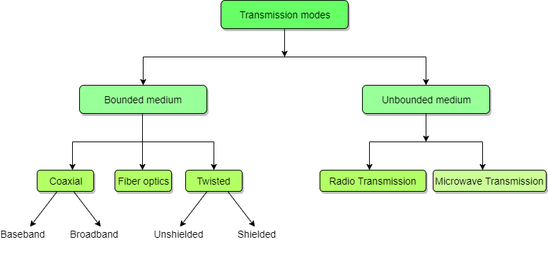
Bounded/Guided Transmission Media
It is the transmission media in which signals are confined to a specific path using wire or cable. The types of Bounded/ Guided are discussed below.
Twisted Pair Cable
This cable is the most commonly used and is cheaper than others. It is lightweight, cheap, can be installed easily, and they support many different types of network. Some important points :
- Its frequency range is 0 to 3.5 kHz.
- Typical attenuation is 0.2 dB/Km @ 1kHz.
- Typical delay is 50 µs/km.
- Repeater spacing is 2km.
Twisted Pair is of two types :
- Unshielded Twisted Pair (UTP)
- Shielded Twisted Pair (STP)
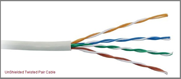
Unshielded Twisted Pair Cable
It is the most common type of telecommunication when compared with Shielded Twisted Pair Cable which consists of two conductors usually copper, each with its own colour plastic insulator. Identification is the reason behind coloured plastic insulation.
UTP cables consist of 2 or 4 pairs of twisted cable. Cable with 2 pair use RJ-11 connector and 4 pair cable use RJ-45 connector.
Advantages :
- Installation is easy
- Flexible
- Cheap
- It has high speed capacity,
- 100 meter limit
- Higher grades of UTP are used in LAN technologies like Ethernet.
It consists of two insulating copper wires (1mm thick). The wires are twisted together in a helical form to reduce electrical interference from similar pair.
Disadvantages :
- Bandwidth is low when compared with Coaxial Cable
- Provides less protection from interference.
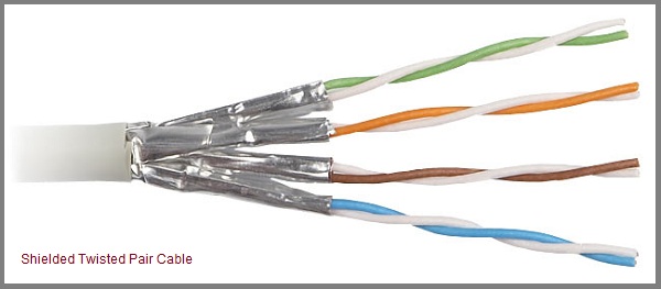
Shielded Twisted Pair Cable
This cable has a metal foil or braided-mesh covering which encases each pair of insulated conductors. Electromagnetic noise penetration is prevented by metal casing. Shielding also eliminates crosstalk (explained in KEY TERMS Chapter).
It has same attenuation as unshielded twisted pair. It is faster the unshielded and coaxial cable. It is more expensive than coaxial and unshielded twisted pair.
Advantages :
- Easy to install
- Performance is adequate
- Can be used for Analog or Digital transmission
- Increases the signalling rate
- Higher capacity than unshielded twisted pair
- Eliminates crosstalk
Disadvantages :
- Difficult to manufacture
- Heavy
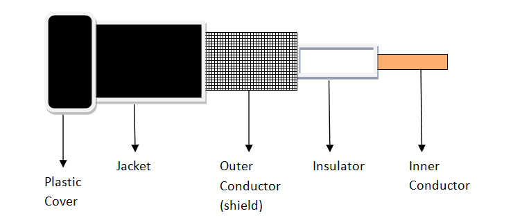
Coaxial Cable
Coaxial is called by this name because it contains two conductors that are parallel to each other. Copper is used in this as centre conductor which can be a solid wire or a standard one. It is surrounded by PVC installation, a sheath which is encased in an outer conductor of metal foil, barid or both.
Outer metallic wrapping is used as a shield against noise and as the second conductor which completes the circuit. The outer conductor is also encased in an insulating sheath. The outermost part is the plastic cover which protects the whole cable.
Here the most common coaxial standards.
- 50-Ohm RG-7 or RG-11 : used with thick Ethernet.
- 50-Ohm RG-58 : used with thin Ethernet
- 75-Ohm RG-59 : used with cable television
- 93-Ohm RG-62 : used with ARCNET.
There are two types of Coaxial cables :
BaseBand
This is a 50 ohm (Ω) coaxial cable which is used for digital transmission. It is mostly used for LAN’s. Baseband transmits a single signal at a time with very high speed. The major drawback is that it needs amplification after every 1000 feet.
BroadBand
This uses analog transmission on standard cable television cabling. It transmits several simultaneous signal using different frequencies. It covers large area when compared with Baseband Coaxial Cable.
Advantages :
- Bandwidth is high
- Used in long distance telephone lines.
- Transmits digital signals at a very high rate of 10Mbps.
- Much higher noise immunity
- Data transmission without distortion.
- The can span to longer distance at higher speeds as they have better shielding when compared to twisted pair cable
Disadvantages :
- Single cable failure can fail the entire network.
- Difficult to install and expensive when compared with twisted pair.
- If the shield is imperfect, it can lead to grounded loop.
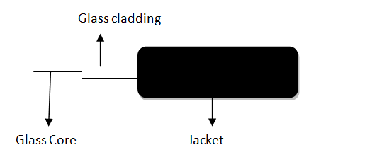
Fiber Optic Cable
These are similar to coaxial cable. It uses electric signals to transmit data. At the centre is the glass core through which light propagates.
In multimode fibres, the core is 50microns, and In single mode fibres, the thickness is 8 to 10 microns.
The core in fiber optic cable is surrounded by glass cladding with lower index of refraction as compared to core to keep all the light in core. This is covered with a thin plastic jacket to protect the cladding. The fibers are grouped together in bundles protected by an outer shield.
Fiber optic cable has bandwidth more than 2 gbps (Gigabytes per Second)
Advantages :
- Provides high quality transmission of signals at very high speed.
- These are not affected by electromagnetic interference, so noise and distortion is very less.
- Used for both analog and digital signals.
Disadvantages :
- It is expensive
- Difficult to install.
- Maintenance is expensive and difficult.
- Do not allow complete routing of light signals.
UnBounded/UnGuided Transmission Media
Unguided or wireless media sends the data through air (or water), which is available to anyone who has a device capable of receiving them. Types of unguided/ unbounded media are discussed below :
- Radio Transmission
- MicroWave Transmission
Radio Transmission
Its frequency is between 10 kHz to 1GHz. It is simple to install and has high attenuation. These waves are used for multicast communications.
Types of Propogation
Radio Transmission utilizes different types of propogation :
- Troposphere : The lowest portion of earth’s atmosphere extending outward approximately 30 miles from the earth’s surface. Clouds, jet planes, wind is found here.
- Ionosphere : The layer of the atmosphere above troposphere, but below space. Contains electrically charged particles.
Microwave Transmission
It travels at high frequency than the radio waves. It requires the sender to be inside of the receiver. It operates in a system with a low gigahertz range. It is mostly used for unicast communication.
There are 2 types of Microwave Transmission :
- Terrestrial Microwave
- Satellite Microwave
Advantages of Microwave Transmission
- Used for long distance telephone communication
- Carries 1000’s of voice channels at the same time
Disadvantages of Microwave Transmission
- It is Very costly
Terrestrial Microwave
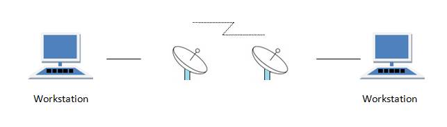
For increasing the distance served by terrestrial microwave, repeaters can be installed with each antenna .The signal received by an antenna can be converted into transmittable form and relayed to next antenna as shown in below figure. It is an example of telephone systems all over the world

There are two types of antennas used for terrestrial microwave communication :
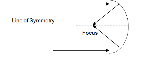
1. Parabolic Dish Antenna
In this every line parallel to the line of symmetry reflects off the curve at angles in a way that they intersect at a common point called focus. This antenna is based on geometry of parabola.
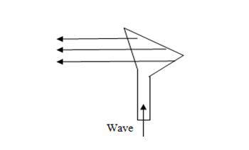
2. Horn Antenna
It is a like gigantic scoop. The outgoing transmissions are broadcast up a stem and deflected outward in a series of narrow parallel beams by curved head.
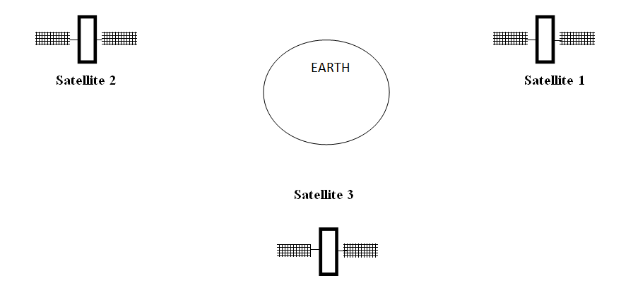
Satellite Microwave
This is a microwave relay station which is placed in outer space. The satellites are launched either by rockets or space shuttles carry them.
These are positioned 36000KM above the equator with an orbit speed that exactly matches the rotation speed of the earth. As the satellite is positioned in a geo-synchronous orbit, it is stationery relative to earth and always stays over the same point on the ground. This is usually done to allow ground stations to aim antenna at a fixed point in the sky.
Features of Satellite Microwave :
- Bandwidth capacity depends on the frequency used.
- Satellite microwave deployment for orbiting satellite is difficult.
Advantages of Satellite Microwave :
- Transmitting station can receive back its own transmission and check whether the satellite has transmitted information correctly.
- A single microwave relay station which is visible from any point.
Disadvantages of Satellite Microwave :
- Satellite manufacturing cost is very high
- Cost of launching satellite is very expensive
- Transmission highly depends on whether conditions, it can go down in bad weather
To Clear English Sections You must Have English Tricks Book Buy Now From Here
Buy Now
To Clear Quantitative Aptitude Section You must Have Quantitative Aptitude Tricks Book Buy Now From Here
Buy Now
To Clear Reasoning Section You must Have Reasoning Tricks Book Buy Now From Here
Buy Now
To Clear Computer Awareness Section You must Have Computer Awareness Book Buy Now From Here
Buy Now
Puzzles & Seating Arrangement Short Tricks Book
Buy Now
Types of Communication Networks
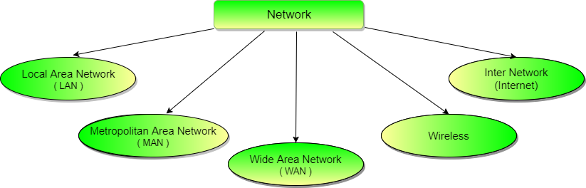
Local Area Network (LAN)
It is also called LAN and designed for small physical areas such as an office, group of buildings or a factory. LANs are used widely as it is easy to design and to troubleshoot. Personal computers and workstations are connected to each other through LANs. We can use different types of topologies through LAN, these are Star, Ring, Bus, Tree etc.
LAN can be a simple network like connecting two computers, to share files and network among each other while it can also be as complex as interconnecting an entire building.
LAN networks are also widely used to share resources like printers, shared hard-drive etc.
Applications of LAN
- One of the computer in a network can become a server serving all the remaining computers called clients. Software can be stored on the server and it can be used by the remaining clients.
- Connecting Locally all the workstations in a building to let them communicate with each other locally without any internet access.
- Sharing common resources like printers etc are some common applications of LAN.
Metropolitan Area Network (MAN)
It is basically a bigger version of LAN. It is also called MAN and uses the similar technology as LAN. It is designed to extend over the entire city. It can be means to connecting a number of LANs into a larger network or it can be a single cable. It is mainly hold and operated by single private company or a public company.
Wide Area Network (WAN)
It is also called WAN. WAN can be private or it can be public leased network. It is used for the network that covers large distance such as cover states of a country. It is not easy to design and maintain. Communication medium used by WAN are PSTN or Satellite links. WAN operates on low data rates.
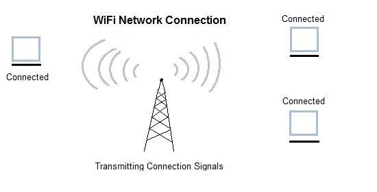
Wireless Network
Digital wireless communication is not a new idea. Earlier, Morse code was used to implement wireless networks. Modern digital wireless systems have better performance, but the basic idea is the same.
Wireless Networks can be divided into three main categories:
- System interconnection
- Wireless LANs
- Wireless WANs
System Interconnection
System interconnection is all about interconnecting the components of a computer using short-range radio. Some companies got together to design a short-range wireless network called Bluetooth to connect various components such as monitor, keyboard, mouse and printer, to the main unit, without wires. Bluetooth also allows digital cameras, headsets, scanners and other devices to connect to a computer by merely being brought within range.
In simplest form, system interconnection networks use the master-slave concept. The system unit is normally the master, talking to the mouse, keyboard, etc. as slaves.
Wireless LANs
These are the systems in which every computer has a radio modem and antenna with which it can communicate with other systems. Wireless LANs are becoming increasingly common in small offices and homes, where installing Ethernet is considered too much trouble. There is a standard for wireless LANs called IEEE 802.11, which most systems implement and which is becoming very widespread.
Wireless WANs
The radio network used for cellular telephones is an example of a low-bandwidth wireless WAN. This system has already gone through three generations.
- The first generation was analog and for voice only.
- The second generation was digital and for voice only.
- The third generation is digital and is for both voice and data.
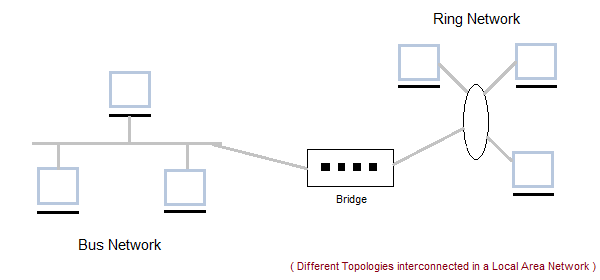
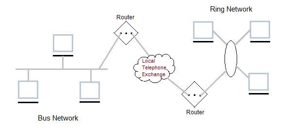
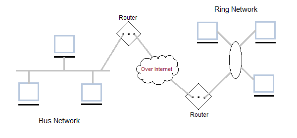
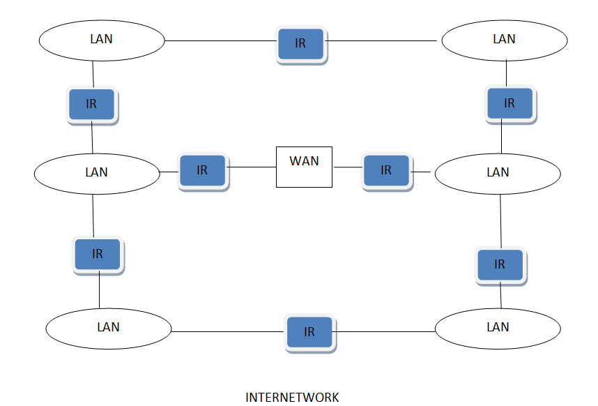
Inter Network
Inter Network or Internet is a combination of two or more networks. Inter network can be formed by joining two or more individual networks by means of various devices such as routers, gateways and bridges.
Connection Oriented and Connectionless Services
These are the two services given by the layers to layers above them. These services are :
- Connection Oriented Service
- Connectionless Services
Connection Oriented Services
There is a sequence of operation to be followed by the users of connection oriented service. These are :
- Connection is established
- Information is sent
- Connection is released
In connection oriented service we have to establish a connection before starting the communication. When connection is established we send the message or the information and then we release the connection.
Connection oriented service is more reliable than connectionless service. We can send the message in connection oriented service if there is an error at the receivers end. Example of connection oriented is TCP (Transmission Control Protocol) protocol.
Connection Less Services
It is similar to the postal services, as it carries the full address where the message (letter) is to be carried. Each message is routed independently from source to destination. The order of message sent can be different from the order received.
In connectionless the data is transferred in one direction from source to destination without checking that destination is still there or not or if it prepared to accept the message. Authentication is not needed in this. Example of Connectionless service is UDP (User Datagram Protocol) protocol.
Difference between Connection oriented service and Connectionless service
- In connection oriented service authentication is needed while connectionless service does not need any authentication.
- Connection oriented protocol makes a connection and checks whether message is received or not and sends again if an error occurs connectionless service protocol does not guarantees a delivery.
- Connection oriented service is more reliable than connectionless service.
- Connection oriented service interface is stream based and connectionless is message based.
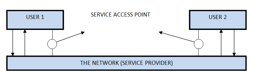
Service Primitives
A service is formally specified by a set of primitives (operations) available to a user process to access the service. These primitives tell the service to perform some action or report on an action taken by a peer entity. If the protocol stack is located in the operating system, as it often is, the primitives are normally system calls. These calls cause a trap to kernel mode, which then turns control of the machine over to the operating system to send the necessary packets. The set of primitives available depends on the nature of the service being provided. The primitives for connection-oriented service are different from those of connection-less service. There are five types of service primitives :
- LISTEN : When a server is ready to accept an incoming connection it executes the LISTEN primitive. It blocks waiting for an incoming connection.
- CONNECT : It connects the server by establishing a connection. Response is awaited.
- RECIEVE: Then the RECIEVE call blocks the server.
- SEND : Then the client executes SEND primitive to transmit its request followed by the execution of RECIEVE to get the reply. Send the message.
- DISCONNECT : This primitive is used for terminating the connection. After this primitive one can’t send any message. When the client sends DISCONNECT packet then the server also sends the DISCONNECT packet to acknowledge the client. When the server package is received by client then the process is terminated.
Connection Oriented Service Primitives
There are 5 types of primitives for Connection Oriented Service :
| LISTEN | Block waiting for an incoming connection |
| CONNECTION | Establish a connection with a waiting peer |
| RECEIVE | Block waiting for an incoming message |
| SEND | Sending a message to the peer |
| DISCONNECT | Terminate a connection |
Connectionless Oriented Service Primitives
There are 4 types of primitives for Connectionless Oriented Service:
| UNIDATA | This primitive sends a packet of data |
| FACILITY, REPORT | Primitive for enquiring about the performance of the network, like delivery statistics. |
Relationship of Services to Protocol
Services
These are the operations that a layer can provide to the layer above it. It defines the operation and states a layer is ready to perform but it does not specify anything about the implementation of these operations.
Protocols
These are set of rules that govern the format and meaning of frames, messages or packets that are exchanged between the server and client.
Reference Models in Communication Networks
The most important reference models are :
- OSI reference model.
- TCP/IP reference model.
Introduction to ISO-OSI Model:
There are many users who use computer network and are located all over the world. To ensure national and worldwide data communication ISO (ISO stands for International Organization of Standardization.) developed this model. This is called a model for open system interconnection (OSI) and is normally called as OSI model.OSI model architecture consists of seven layers. It defines seven layers or levels in a complete communication system. OSI Reference model is explained in other chapter.
Introduction to TCP/IP REFERENCE Model
TCP/IP is transmission control protocol and internet protocol. Protocols are set of rules which govern every possible communication over the internet. These protocols describe the movement of data between the host computers or internet and offers simple naming and addressing schemes.
TCP/IP Reference model is explained in details other chapter.
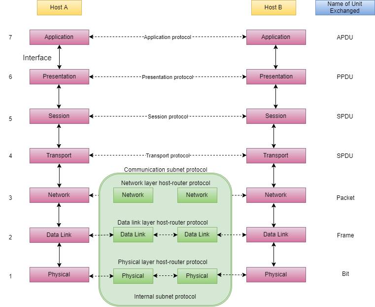
ISO/OSI Model in Communication Networks
There are n numbers of users who use computer network and are located over the world. So to ensure, national and worldwide data communication, systems must be developed which are compatible to communicate with each other. ISO has developed this. ISO stands for International organization of Standardization. This is called a model for Open System Interconnection (OSI) and is commonly known as OSI model.
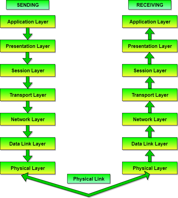
The ISO-OSI model is a seven layer architecture. It defines seven layers or levels in a complete communication system.
Feature of OSI Model :
- Big picture of communication over network is understandable through this OSI model.
- We see how hardware and software work together.
- We can understand new technologies as they are developed.
- Troubleshooting is easier by separate networks.
- Can be used to compare basic functional relationships on different networks.
Functions of Different Layers :
Layer 1: The Physical Layer :
- It is the lowest layer of the OSI Model.
- It activates, maintains and deactivates the physical connection.
- It is responsible for transmission and reception of the unstructured raw data over network.
- Voltages and data rates needed for transmission is defined in the physical layer.
- It converts the digital/analog bits into electrical signal or optical signals.
- Data encoding is also done in this layer.
Layer 2: Data Link Layer :
- Data link layer synchronizes the information which is to be transmitted over the physical layer.
- The main function of this layer is to make sure data transfer is error free from one node to another, over the physical layer.
- Transmitting and receiving data frames sequentially is managed by this layer.
- This layer sends and expects acknowledgements for frames received and sent respectively. Resending of non-acknowledgement received frames is also handled by this layer.
- This layer establishes a logical layer between two nodes and also manages the Frame traffic control over the network. It signals the transmitting node to stop, when the frame buffers are full.
Layer 3: The Network Layer :
- It routes the signal through different channels from one node to other.
- It acts as a network controller. It manages the Subnet traffic.
- It decides by which route data should take.
- It divides the outgoing messages into packets and assembles the incoming packets into messages for higher levels.
Layer 4: Transport Layer :
- It decides if data transmission should be on parallel path or single path.
- Functions such as Multiplexing, Segmenting or Splitting on the data are done by this layer
- It receives messages from the Session layer above it, convert the message into smaller units and passes it on to the Network layer.
- Transport layer can be very complex, depending upon the network requirements.
Transport layer breaks the message (data) into small units so that they are handled more efficiently by the network layer.
Layer 5: The Session Layer :
- Session layer manages and synchronize the conversation between two different applications.
- Transfer of data from source to destination session layer streams of data are marked and are resynchronized properly, so that the ends of the messages are not cut prematurely and data loss is avoided.
Layer 6: The Presentation Layer :
- Presentation layer takes care that the data is sent in such a way that the receiver will understand the information (data) and will be able to use the data.
- While receiving the data, presentation layer transforms the data to be ready for the application layer.
- Languages(syntax) can be different of the two communicating systems. Under this condition presentation layer plays a role of translator.
- It perfroms Data compression, Data encryption, Data conversion etc.
Layer 7: Application Layer :
- It is the topmost layer.
- Transferring of files disturbing the results to the user is also done in this layer. Mail services, directory services, network resource etc are services provided by application layer.
- This layer mainly holds application programs to act upon the received and to be sent data.
Merits of OSI reference model:
- OSI model distinguishes well between the services, interfaces and protocols.
- Protocols of OSI model are very well hidden.
- Protocols can be replaced by new protocols as technology changes.
- Supports connection oriented services as well as connectionless service.
Demerits of OSI reference model:
- Model was devised before the invention of protocols.
- Fitting of protocols is tedious task.
- It is just used as a reference model.
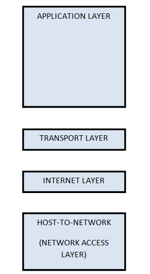
The TCP/IP Reference Model
TCP/IP means Transmission Control Protocol and Internet Protocol. It is the network model used in the current Internet architecture as well. Protocols are set of rules which govern every possible communication over a network. These protocols describe the movement of data between the source and destination or the internet. These protocols offer simple naming and addressing schemes.
Overview of TCP/IP reference model
TCP/IP that is Transmission Control Protocol and Internet Protocol was developed by Department of Defence’s Project Research Agency (ARPA, later DARPA) as a part of a research project of network interconnection to connect remote machines.
The features that stood out during the research, which led to making the TCP/IP reference model were:
- Support for a flexible architecture. Adding more machines to a network was easy.
- The network was robust, and connections remained intact untill the source and destination machines were functioning.
The overall idea was to allow one application on one computer to talk to(send data packets) another application running on different computer.
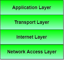
Description of different TCP/IP protocols
Layer 1: Host-to-network Layer
- Lowest layer of the all.
- Protocol is used to connect to the host, so that the packets can be sent over it.
- Varies from host to host and network to network.
Layer 2: Internet layer
- Selection of a packet switching network which is based on a connectionless internetwork layer is called a internet layer.
- It is the layer which holds the whole architecture together.
- It helps the packet to travel independently to the destination.
- Order in which packets are received is different from the way they are sent.
- IP (Internet Protocol) is used in this layer.
Layer 3: Transport Layer
- It decides if data transmission should be on parallel path or single path.
- Functions such as multiplexing, segmenting or splitting on the data is done by transport layer.
- The applications can read and write to the transport layer.
- Transport layer adds header information to the data.
- Transport layer breaks the message (data) into small units so that they are handled more efficiently by the network layer.
- Transport layer also arrange the packets to be sent, in sequence.
Layer 4: Application Layer
The TCP/IP specifications described a lot of applications that were at the top of the protocol stack. Some of them were TELNET, FTP, SMTP, DNS etc.
- TELNET is a two-way communication protocol which allows connecting to a remote machine and run applications on it.
- FTP(File Transfer Protocol) is a protocol, that allows File transfer amongst computer users connected over a network. It is reliable, simple and efficient.
- SMTP(Simple Mail Transport Protocol) is a protocol, which is used to transport electronic mail between a source and destination, directed via a route.
- DNS(Domain Name Server) resolves an IP address into a textual address for Hosts connected over a network.
Merits of TCP/IP model
- It operated independently.
- It is scalable.
- Client/server architecture.
- Supports a number of routing protocols.
- Can be used to establish a connection between two computers.
Demerits of TCP/IP
- In this, the transport layer does not guarantee delivery of packets.
- The model cannot be used in any other application.
- Replacing protocol is not easy.
- It has not clearly separated its services, interfaces and protocols.
To Clear English Sections You must Have English Tricks Book Buy Now From Here
Buy Now
To Clear Quantitative Aptitude Section You must Have Quantitative Aptitude Tricks Book Buy Now From Here
Buy Now
To Clear Reasoning Section You must Have Reasoning Tricks Book Buy Now From Here
Buy Now
To Clear Computer Awareness Section You must Have Computer Awareness Book Buy Now From Here
Buy Now
Puzzles & Seating Arrangement Short Tricks Book
Buy Now